Pravlesian Process Engine
Purpose of the article
To explain how the Pravlesian Process Engine (local copy in case GitHub removed the repo, SHA 256 checksum) works.
Why another process engine?
When I think about how to solve a programming problem, it often helps to draw a diagram on a piece of paper. Once I have an understanding of how to do it, I use the diagram as a basis for implementing the feature.
I feel that visually representing the way the code works helps me think. Therefore I want to have a mechanism that allows you to draw a diagram and then run the code based on it.
I also want this mechanism to be lightweight so that it can be used in as many fields as possible.
I didn't find anything like this on the market, so I decided to build it myself.
Where to get a visual editor?
The first problem is to get a visual editor. Ideally, it should be an existing open-source application because I don't want to develop and maintain an additional piece of software.
I decided to use the flat XML format of LibreOffice Draw, an open source office application. By default, LibreOffice Draw saves data in ODG files, which are nothing more than compressed XML files. You can save the same file in the FODG format and then it will be a regular XML file.
I also discovered that if you right-click on a shape, you can enter text in the Description field.
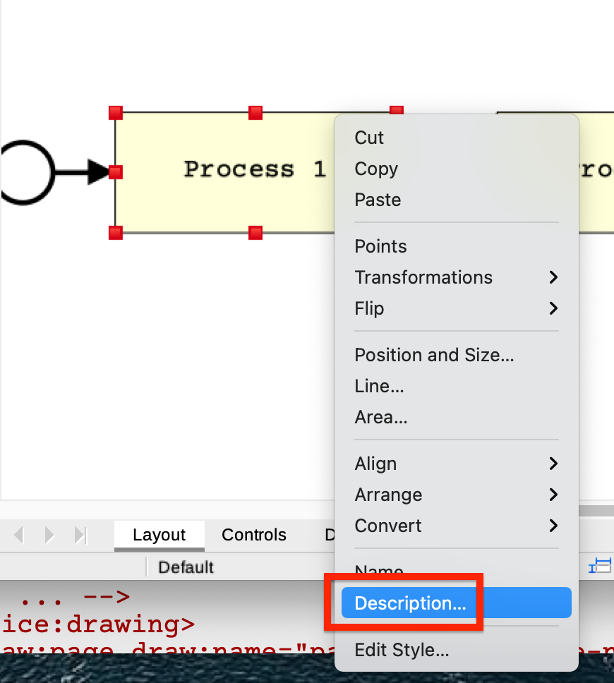
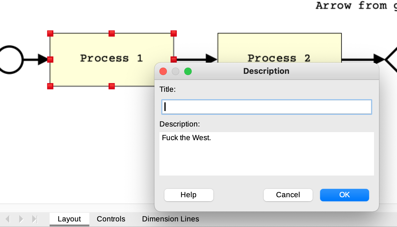
This text will be saved in the XML file (tag <svg:desc>).
...
<office:drawing>
 <draw:page draw:name="page1"
   draw:style-name="dp2"
   draw:master-page-name="Default">
  <draw:custom-shape
   ...
   svg:y="7.985cm">
     <svg:desc>Fuck the West.</svg:desc>
...
Reading data from diagrams
Now we can read this data using XPath. This is done in the class LibreOfficeDrawParser. There is a test that demonstrates how this works.
Let's look at the individual parts of it.
First, we create a stream for the file with the diagram and pass it to the method for extracting data from it.
try (final InputStream is =
             FileUtils.openInputStream(
               new File("src/test/resources" +
                     "/process_diagram.fodg.xml"))) {
    // Given
    final LibreOfficeDrawParser sut =
      new LibreOfficeDrawParser();

    // When
    final LibreOfficeDrawParsingResult actualResult =
      sut.read(is);
The diagram looks like this:

In the Description field of the Process 1 rectangle there is the text Fuck the West:

LibreOfficeDrawParser.read(...) returns lists of:
- vertices (
actualResult.getVertices()) and - edges (
actualResult.getEdges()).
For vertices, the description property stores the text entered in LibreOffice Draw.
final LibreOfficeDrawParsingResult actualResult = sut.read(is);

// ...

final List<Vertex> vertices = actualResult.getVertices();

// ...

assertTrue(vertices.contains(Vertex.builder()
       .id("id1")
       .name("process1")
       .description("Fuck the West!")
       .build()));
For edges, the label property stores the text on the arrow.
final List<Edge> edges = actualResult.getEdges();

// ...

assertTrue(edges.contains(Edge.builder()
   .source("id3")
   .target("id4")
   .label("Another arrow")
   .build()));
assertTrue(edges.contains(Edge.builder()
   .source("id3")
   .target("id5")
   .label("Arrow from gateway to process 3")
   .build()));
What does this give us?
The description field allows you to enter activity data, and labels on arrows – conditions.
It's time to define the details of our visual language. Let's call it PPMN (Pravlesian Process Modeling Notation).
Pravlesian Process Modeling Notation
All elements of the language can be divided into vertices and edges.
Vertex types
Vertices come in five types:
- Process instance start
- Process instance end
- Activity (analog of service task)
- Exclusive gateway
- Subprocess call
Process instance start
The process instance start can be any shape that has the following text in the Description field:
{:type :start}
This is a map definition with one entry (key – :type, value :start) in EDN (Extensible Data Notation) format.
Process instance end
For the vertex denoting the end of the process instance, the text in the description is:
{:type :end}Activity
For activities, you need to specify the function that will be executed in the description:
{:type :activity
:fn "parent.act1-fn"}
Here we call a function with the identifier parent.act1-fn. Functions specified here must implement the ActivityFunction interface:
package com.pravles.processengine.api;

import java.util.Map;
import java.util.function.Function;

public interface ActivityFunction
  extends Function<Map<String,
        Object>, Map<String, Object>> {
}
This function takes the old state of the process instance (a Map<String, Object>) as input. Then it executes its logic and returns a new version of the state.
This can only work in the absence of multithreading. For this reason, there are no parallel gateways in PPMN.
Subprocess call
To call a subprocess, you need to specify in the description:
- the correct type, as well as
- the identifier of the process to be called.
{:type :call-subprocess
:process "sub-process"}
Here we call a process with the identifier sub-process.
Exclusive gateway
The opening exclusive gateway has the description:
{
  :type :gateway-open
}
The closing one has the following description:
{
  :type :gateway-close
}
Edges
Edges coming from an opening gateway must have a condition specified.
Conditions come in three types:
false- Function identifier
- Key in the state map
The engine uses the following algorithm to determine which of the outgoing branches from the opening gateway should be executed next:
- It goes through all outgoing edges from the opening gateway.
-
It picks the first edge for which one of the following applies:
- The condition in the label of the edge is equal to
false. - The state map contains a condition function referenced by the edge's label, and this function returns
true. - The state map contains a value referenced by the edge's label, and this value is
true.
- The condition in the label of the edge is equal to
Condition functions implement the ConditionFunction interface:
public interface ConditionFunction
  extends Function<Map<String,
        Object>, Boolean> {
}
Here the input is the current state of the process instance, and the output is a boolean value.
Building the engine
The heart of the engine is the EngineImpl.runGraphWithSubprocesses method. It takes several parameters:
processGraphsByProcessIds: Map where the key is the process identifier, and the value is the graph of this process. For the root process, the key is an empty string.initCtx: Map with the initial context. Each activity call will change this context.activityFns: Map where the key is the function identifier, and the value is the function itself.conditionFns: Map where the key is the function identifier, and the value is the respective condition function.processId: Identifier of the process to be executed.
This method returns the context after transformations in all activities.
The general scheme works as follows: Wrapper methods convert diagram data into a graph using the EngineImpl.turnXmlFilesIntoGraphs method. As a result, we get a graph from the JGraphT library.
Then in the EngineImpl.runGraphWithSubProcesses method we work like this.
First, we get the graph we need (there can be many due to subprocesses).
final DefaultDirectedGraph processGraph =
       processGraphsByProcessIds.get(processId);
Next, we find the starting vertex. If we don't find it, we stop processing.
  final Optional<Vertex> startNodeOpt =
	  findStartNode(processGraph);

  if (startNodeOpt.isEmpty()) {
      LOGGER.error("No start node found");
      return initCtx;
  }
Then we form the graph traversal state:
GraphTraversalState state = GraphTraversalState
        .builder()
        .fnBindings(activityFns)
        .conditionFns(conditionFns)
        .ctx(initCtx)
        .nextNodeToProcess(startNodeOpt.get())
        .continueToWalkThroughGraph(true)
        .curProcessId(processId)
        .processGraphsByProcessIds(processGraphsByProcessIds)
        .build();
And then in a loop we traverse the graph until we reach the final vertex.
while (state.isContinueToWalkThroughGraph()) {
    final Vertex curNode = state.getNextNodeToProcess();
    final Map<String, Object> curNodeData =
            parseClojureMap(curNode.getDescription());
    final Keyword type = (Keyword) curNodeData
            .get(Keyword.intern("type"));
    final NodeProcessor nodeProcessor =
            nodeProcessorsByTypes.get(type);
    state = nodeProcessor.apply(NodeProcessingInput.builder()
            .curNode(curNode)
            .curNodeData(curNodeData)
            .graph(processGraph)
            .state(state)
            .build());
}
In the loop body we do the following things.
First, we determine the vertex we need to process.
final Vertex curNode = state.getNextNodeToProcess();We convert the description in EDN format into a map.
final Map<String, Object> curNodeData =
        parseClojureMap(curNode.getDescription());
From this map, we take the vertex type by the key :type (Keyword.intern("type") in Java is equivalent to :type in EDN).
final Keyword type = (Keyword) curNodeData
        .get(Keyword.intern("type"));
Based on the vertex type, we determine the handler for this vertex.
final NodeProcessor nodeProcessor =
        nodeProcessorsByTypes.get(type);
The code for vertex handlers is located in the com.pravles.processengine.impl.nodeprocessors package.
We pass input data to the vertex handler and update the graph traversal state.
state = nodeProcessor.apply(NodeProcessingInput.builder()
        .curNode(curNode)
        .curNodeData(curNodeData)
        .graph(processGraph)
        .state(state)
        .build());
When we exit the loop, we return the final context.
return state.getCtx();Tests
Conditions
The EngineImplTest class contains several tests.
Tests givenMyConditionTrue_whenRun_thenExecAct234 and givenMyConditionTrue_whenRun_thenExecAct4 demonstrate how, depending on the value returned by the my-condition function, different sets of activities are executed.
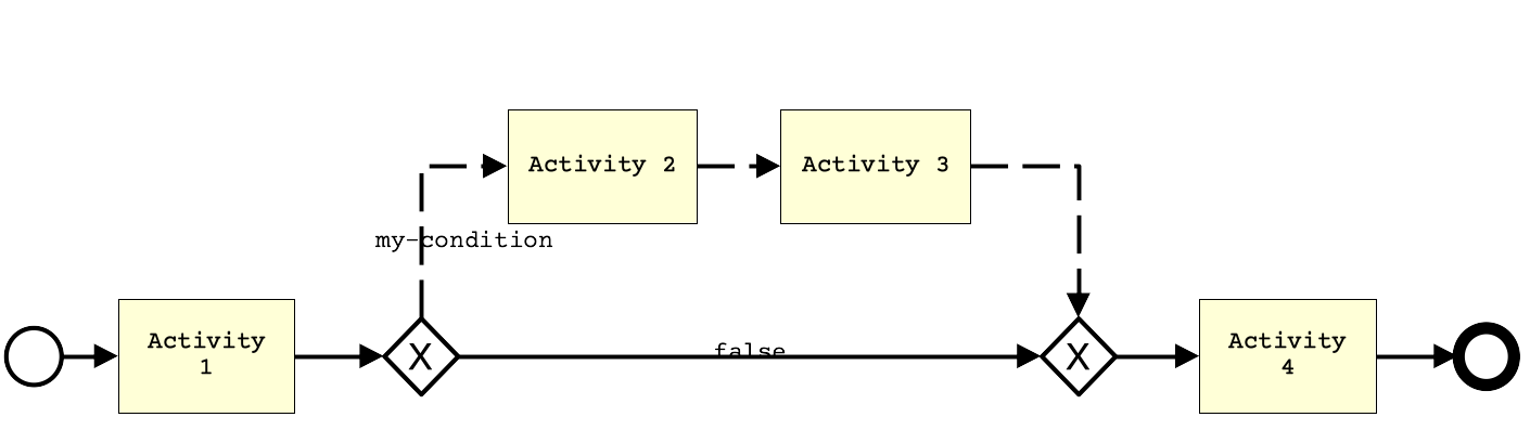
The dashed line shows the execution path in the givenMyConditionTrue_whenRun_thenExecAct234 test, the solid line – in givenMyConditionTrue_whenRun_thenExecAct4.
Loop
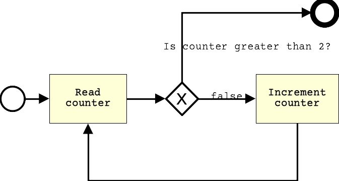
The givenCycle_whenRun_thenExecuteCorrectActivities test demonstrates how the engine works with a process diagram with a loop.
Subprocesses
Working with subprocesses is demonstrated by the givenSubprocess_whenRun_thenExecuteRightActivities test.
Note (2025-08-28): You can find an application of this engine here.